Geometric Design Lab - Lab 04
Pavement Edge Design with a Simple Arc of a Circle and with a Taper Section and an Arc of
a Circle using MicroStation
Copyright © 2009 by Dr. Thomas W. Rioux
Students taking this course may print one copy of this document for their
personal class use.
Objective: Learn pavement edge design and vehicle offtracking
concepts using IGIDS-created vehicle turn template. Observe the reduction in
circular arc radius and area when a taper section is added.
Activity: Copy the MicroStation Cell Library file "bus_template.cel" to "Z:\MicroStation"; Start MicroStation and create a 2D design file "Z:\MicroStation\lab_04.dgn" using the seed file "Z:\MicroStation\train2d.dgn"; Use MicroStation to draw the legs of the intersection; Attach the cell file "bus_template.cel"; Place the IGIDS BUS Template cell; Construct a circular arc curb return; Use MicroStation to draw the 1:10 taper section line; Use MicroStation to construct a circular arc pavement edge; Use MicroStation to extend the taper section line to the green circular arc; Use MicroStation to measure, crosshatch, and dimension the area between the two pavement edges; Use MicroStation to dimension the two circular arcs and the taper section; Turn Level 1 display on; Place a landscape oriented rectangle centered around the intersection in 8.5" by 11" proportion (230 feet by 180 feet); Place the title "Lab Assignment 04" at the top right and your name, class name, and assignment due date in the lower right; Place a fence from the rectangle and plot the drawing; Exit MicroStation; and Reboot the computer.
Background: The California Department of Transportation (CALTRANS) developed the Truck Offtracking Model (TOM), a computer model of vehicle offtracking. The Texas State Department of Transportation (TxDOT) modified TOM and called it TXTOM. TXTOM was used to generate the vehicle turn templates found in the American Association of State Highway and Transportation Officials (AASHTO) design policy. The Center for Transportation Research at The University of Texas at Austin converted TXTOM from FORTRAN to C, added metric units, added metric parameters for the design vehicles, and incorporated TXTOM in the Interactive Graphics Intersection Design System (IGIDS). For the standard AASHTO design vehicles, vehicle turning templates may be quickly drawn to a user-specified turn radius for the turn angle between adjacent, user-selected legs. The position of the outer edge of the front bumper and the inner edge of the rear axle are calculated as the outer edge of the front axle is moved in 1-foot (0.3048-foot) increments along a circular arc. An optional clearance zone in yellow may be specified that is calculated the specified distance outside the outer edge of the front bumper and inside the inner edge of the rear axle. These templates are created as a MicroStation Cell. A MicroStation Cell is a group of elements with an optional placement origin which can be manipulated as a single element. A MicroStation Cell is contained in a MicroStation Cell Library which can have one or more MicroStation Cells. These templates may be moved dynamically over the intersection geometry to evaluate pavement edge and channelization requirements.
A taper section is a line segment at a shallow angle to the pavement edge expressed as a ratio of lateral distance to longitudinal distance, usually in the range of 1:10 to 1:15. The taper section may precede and/or follow the circular arc. The use of taper sections can facilitate fitting the pavement edge to the offtracking path of a selected design vehicle and generally reduces the radius of the circular arc.
A. Copy the MicroStation Cell Library
file "bus_template.cel" to "Z:\MicroStation"
.
A.1. Start -> All Programs -> Internet Explorer.
A.2. In Internet Explorer, choose Tools -> Internet Options.
A.3. In the Internet Options window, select Advanced. In the Settings area, scroll to Browsing, uncheck Use Passive FTP, and press the OK push button.
A.4. In Internet Explorer, go to ftp://ftp.ce.utexas.edu/class/rioux/GeometricDesignLab.
A.5. Put your cursor over the file bus_template.cel, click the right mouse button, and choose "Save Target As..." or "Save Link As..." or "Save to Folder" or "Copy to Folder...".
A.6. In the Save As... or Browse For Folder dialog box, choose My Computer then Home Directory (Z:) then MicroStation, and finally press the Save or OK push button.
B. Start MicroStation and create a 2D design file "Z:\MicroStation\lab_04.dgn" using the seed file "Z:\MicroStation\train2d.dgn".
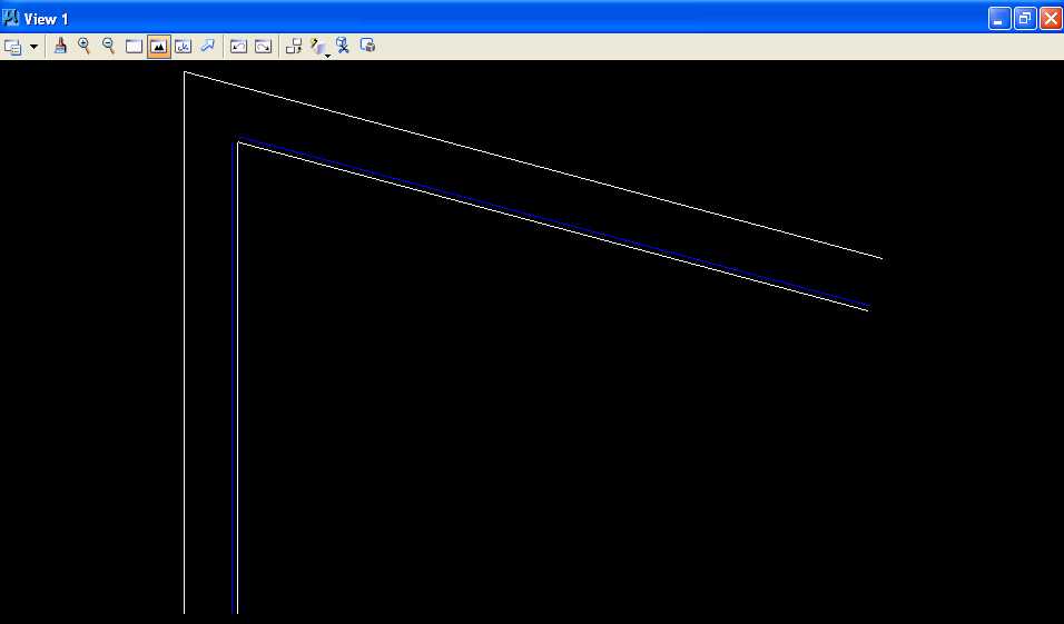
C. Use MicroStation to draw the legs of the intersection.
C.1. Set the active level to Level 2 (level=Level 2), the color to white (color=0), the style to solid (style=0), and the weight to 0 (weight=0).
C.2. From point 5000,5000, draw a 150 foot line at an angle of 270 degrees (Line A).
C.3. From point 5000,5000, draw a 200 foot line at an angle of 345 degrees (Line B).
C.4. Copy Line A a distance of 15 feet parallel to the right (Line C).
C.5. Copy Line B a distance of 15 feet parallel to the bottom (Line D).
C.6. Extend lines C and D to their intersection.
C.7. Copy Line C a distance of 1.5 feet parallel to the left (Line E).
C.8. Copy Line D a distance of 1.5 feet parallel to the top (Line F).
C.9. Change the color of Line E and Line F to blue (color=1).
C.10. Fit window 1.
D. Attach the cell file "bus_template.cel".
D.1. From the MicroStation dialog box, choose Element -> Cells.
D.2. In the Cell Library: [NONE] dialog box, choose File -> Attach File.
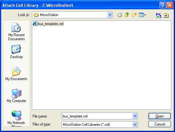
D.3. In the Attach Cell Library dialog box under Look in:, choose My Computer then Home Directory (Z:) then MicroStation; under Files of type, choose MicroStation Cell Libraries (*.cel); choose bus_template.cel; and press the Open push button.
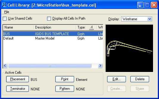
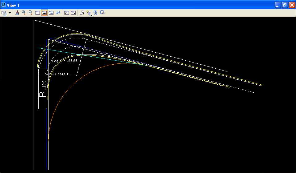
D.4. In the Cell Library: [Z:\MicroStation\bus_template.cel] dialog box under Name, choose BUS and under Active Cells select Placement. IGIDS was used to generate this vehicle turn template for a Bus with a turn radius of 38 feet, with a 1 foot clearance zone (yellow lines), and with a turn angle of 105 degrees.
D.5. Close
the Cell Library: [Z:\MicroStation\bus_template.cel] dialog box
by pressing  in the
upper right corner.
in the
upper right corner.
D.6. From the MicroStation dialog box, choose File -> Save Settings.
E. Place the IGIDS BUS Template cell on Level 1.
Note: It's important to set working units to feet and resolution to 1000000 per foot before placing the cell (see section C.10 in lab 01).
E.1. Set the active level to Level 1 (level=Level 1).
E.2. From the MicroStation Main Tool menu, select the Cells palette (6th row right icon).
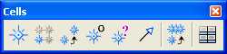
E.3. From the Cells palette, select the
Place Active Cell icon (first icon from the left)
![]() .
.
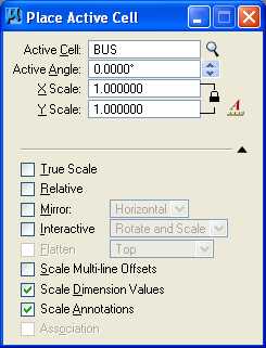
E.4. In the Place Active Cell dialog box, ensure that the Active Cell is BUS, the Active Angle is 0.0, X Scale is 1.0, Y Scale is 1.0, the scale is locked, True Scale is unset, Relative is unset (the BUS cell was created on Level 1), Mirror is unset, Interactive is unset, Scale Multi-line Offsets is unset, Scale Dimension Values is set, and Scale Annotations is set.
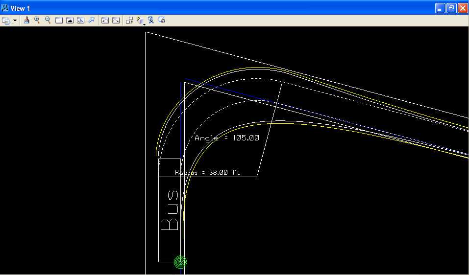
E.5. Position the vehicle turn template so that the inside rear axle
path of the bus (right solid white line of the vehicle turn template) is touching Line E (blue
vertical line) (green bulls eye below) (Hint:
you may want to place the cell in the approximate location then use the Move
command, identify the element using the Keypoint Snap
 to the inside rear axle path of the bus, and identify
the final point using the Nearest Snap Point
to the inside rear axle path of the bus, and identify
the final point using the Nearest Snap Point
 to Line E)
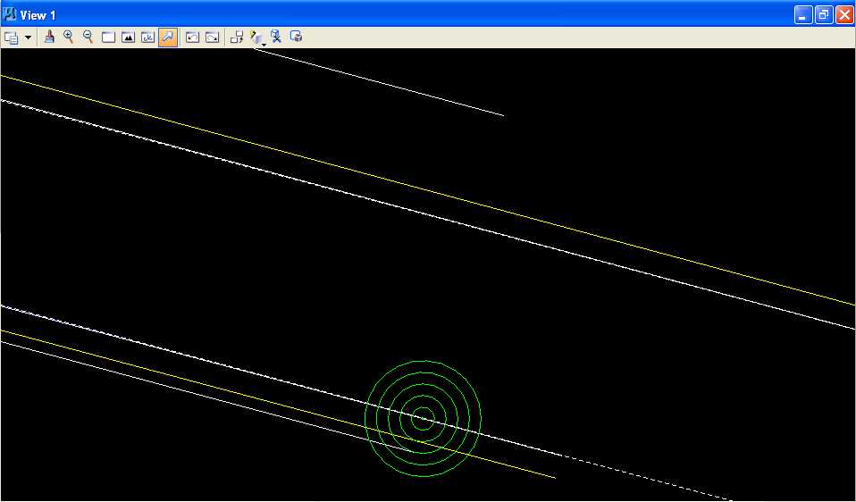
and that the inside rear axle path of the bus (right solid
white line of the
vehicle turn template) is touching at the end of Line F (blue line at angle) (green bulls eye below) (Hint: you may want to use the Move
command with Settings -> Locks -> Axis, identify the element using the
Keypoint Snap
to the inside rear axle path of the bus, identify the
final point using a Data Point near Line E, Zoom In, and repeat as necessary; be
sure to turn Settings -> Locks -> Axis off ).
E.6. Ensure that the yellow clearance lines of the vehicle turn template are inside the adjacent lane edges at the top (Line B) and bottom on the right (Line D).
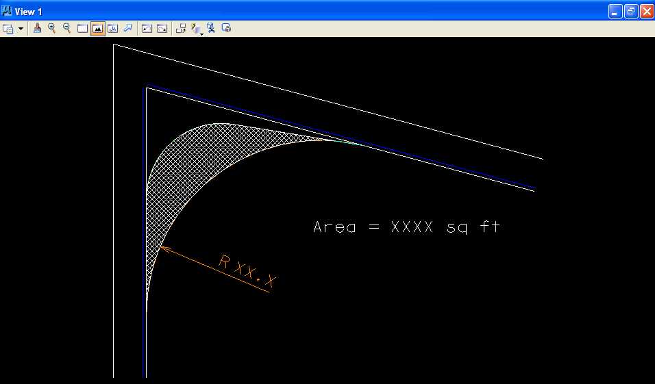
F. Construct a circular arc curb return.
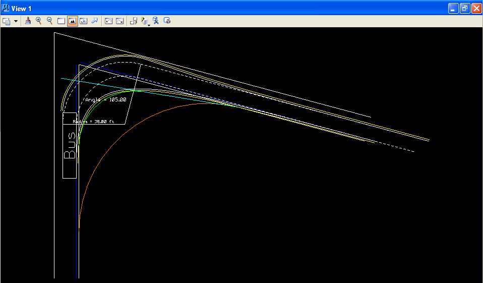
F.1. Set the active level to Level 2 (level=Level 2) and the active color to orange (color=6).
F.2. Construct a circular fillet using Line C and Line D.
F.2.a. From the MicroStation Main Tool menu, select the Modify palette (last row right icon).
F.2.b. From the Modify palette, press the Construct Circular Fillet icon (next to the last icon from the left).
F.2.c. In the Construct Circular Fillet dialog box, enter a Radius of 50 feet and set the Truncate option to None.
F.2.d. Move the cursor over Line C and press the Data button; Line C should be highlighted. Move the cursor over Line D and press the Data button; Line D should also be highlighted and a circular fillet of 50 feet drawn. (Hint: you may want to open Window 2, make the size of Window 2 very small, and zoom in Window 2 very close on the intersection of Line C and Line D and then zoom in Window 1 near where the orange circular fillet is closest to the inside rear axle yellow clearance path; be sure to use the zoom controls for each window.)
F.2.e. If the orange circular fillet crosses the inside rear axle yellow clearance path then Undo the Circular Filet by choosing Edit -> Undo Circular Filet (no truncation) and repeat instructions F.2.c through F.2.d changing the radius in 5-foot increments and then 1-foot increments and then 0.1-foot increments until the minimum radius orange circular fillet is found that does not cross the inside rear axle yellow clearance path.
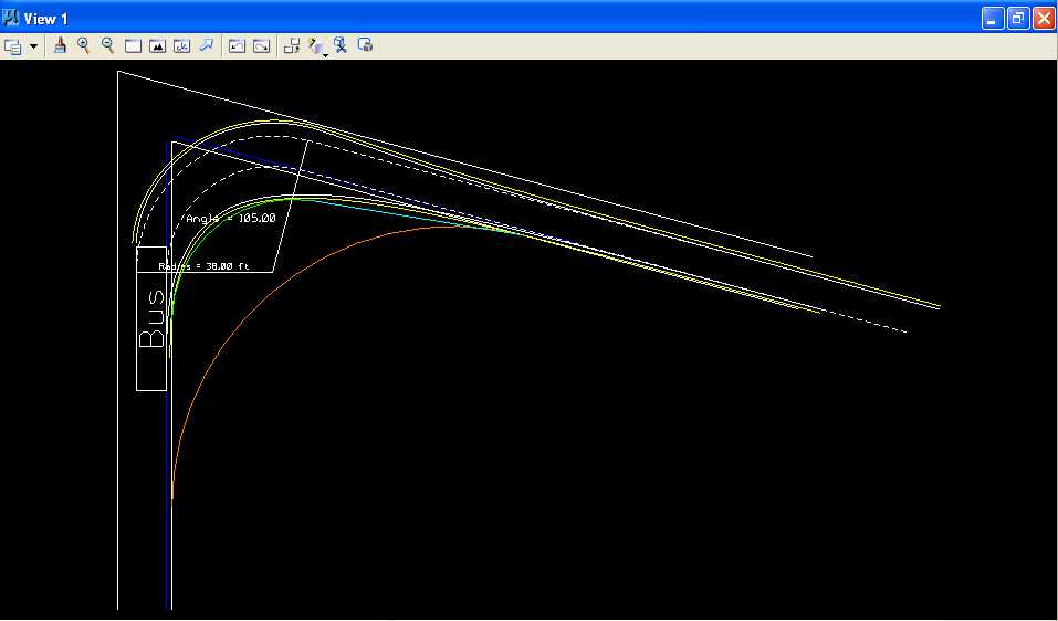
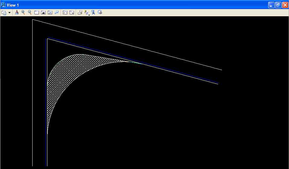
G. Use MicroStation to draw the 1:10 taper section line.
G.1. Set the active color to light blue (color=7).
G.2. From the intersection of Line D (the bottom edge of the lane on the
right (white line)) and the inner edge yellow clearance line of the vehicle turn template,
draw a 110 foot 1:10 taper section line relative to Line D towards Line C (the right edge
of the lane on the left (white line)) as shown below (Hint:
Line D was placed at an angle of 165 degrees; use
Start -> All Programs -> Accessories -> Calculator with View -> Scientific to determine
the angle for the 1:10 taper section using the inverse tangent function; use
4 decimal
points of accuracy for the angle; then use the calculator to add the 165 degrees to find
the angle for the taper section line) (Hint: you may want
to use the intersect snap  when placing
the taper section line; because the inner edge yellow clearance line is a line string made
up of many short (less than 1 foot) line segments, you have to zoom in very close to
the intersection of the 2 lines to make the intersect snap work properly; the intersect
snap will project whatever short line segment you choose to intersect with the other line
even if another short line segment actually crosses the line at another place).
when placing
the taper section line; because the inner edge yellow clearance line is a line string made
up of many short (less than 1 foot) line segments, you have to zoom in very close to
the intersection of the 2 lines to make the intersect snap work properly; the intersect
snap will project whatever short line segment you choose to intersect with the other line
even if another short line segment actually crosses the line at another place).
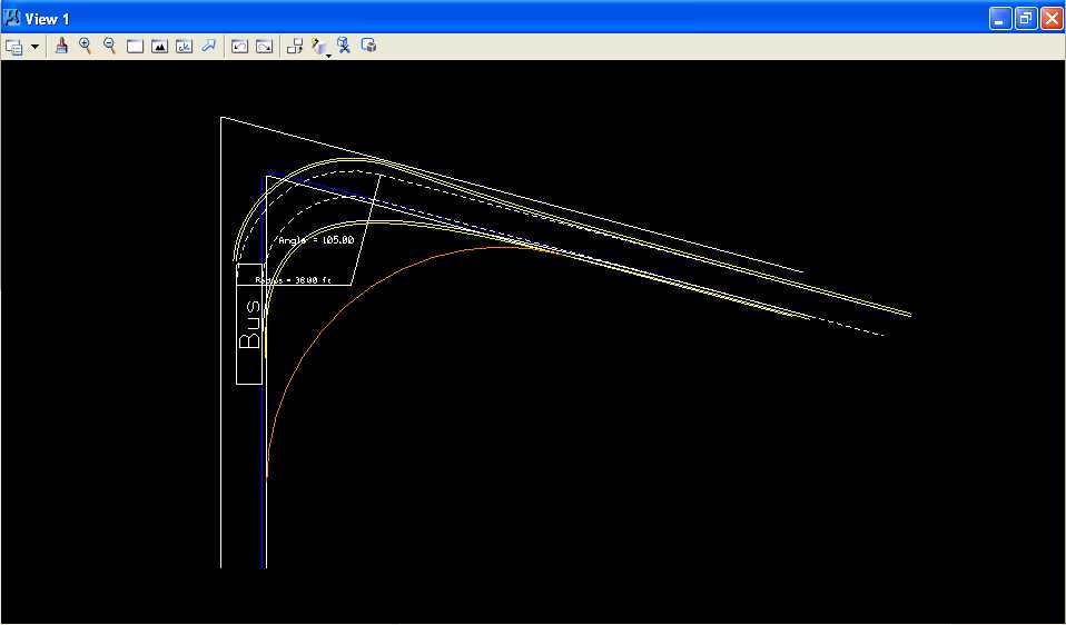
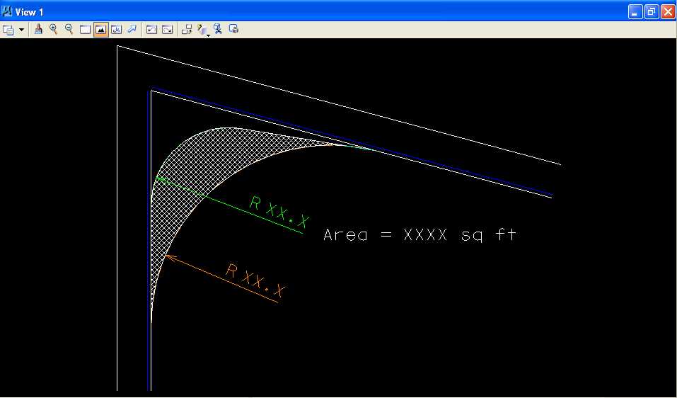
H. Use MicroStation to construct a circular arc pavement edge.
H.1. Set the active color to green (color=2).
H.2. Construct a circular fillet using Line C (the right edge of the lane at the bottom (white line)) and the taper section line starting with a radius of 50 feet with the Truncate option set to none. Repeat the construction of the green circular fillet changing the radius in 5-foot increments and then 1-foot increments and then 0.1 foot increments until the minimum radius green circular fillet is found such that the inner rear axle yellow clearance path does not cross the green circular fillet. (Hint: you may want to open Window 2, make the size of Window 2 very small, and zoom in Window 2 very close on the intersection of Line C and the taper section line and then zoom in Window 1 near where the green circular fillet is closest to the inside rear axle yellow clearance path; be sure to use the zoom controls for each window.)
I. Use MicroStation to extend the taper section line to the green circular arc.
I.1. From the MicroStation tool palette, select the Modify palette (last row right icon).
I.2. From the Modify palette, choose the Extend Element to Intersection
icon (5th icon from left)
 .
.
I.3. Place the cursor over the taper section line to the right of the
green circular arc and press the Data button; the taper section line should be
highlighted. Place the cursor over the green circular arc and press the
Data button; the circular arc should also be highlighted and the taper
section line extended (shortened) to the circular arc. If this command does not seem to work, you may have
to use the Extend Element icon (3rd icon from left)
 to extend (shorten) the taper section line to
the circular arc.
to extend (shorten) the taper section line to
the circular arc.
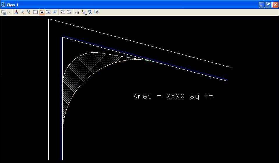
J. Use MicroStation to measure, crosshatch, and dimension the area between the two pavement edges.
J.1. Turn Level 1 display off.
J.1.a. In the MicroStation window, choose Settings -> Level -> Display.
J.1.b. In the Level Display dialog box, set Level 1 to off and close the Level Display dialog box (this should cause the vehicle turn template to be not displayed).
J.2. Measure Area the area between the two pavement edges (setting Method to Flood and clicking in the area bound by the two circular fillets) and record the value of the area to the nearest integer number.
J.3. Set the active color to white (color=0).
J.4. From the MicroStation tool palette, choose the Patterns palette (3rd row left icon).
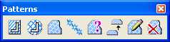
J.5. From the Patterns palette, choose the Crosshatch Area icon (2nd icon
from the left)
 .
.
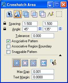
J.6. From the Crosshatch Area dialog box,
press the Flood icon
 ,
set Lock Spacing by pressing the lock to the left of the Spacing
label, set Spacing to
1.5, set Angle to 45, set
Tolerance to 0, set Associative Pattern
to on, set Associative Region
Boundary to off, set Snappable Pattern to off,
press the Ignore Interior Shapes icon
,
set Lock Spacing by pressing the lock to the left of the Spacing
label, set Spacing to
1.5, set Angle to 45, set
Tolerance to 0, set Associative Pattern
to on, set Associative Region
Boundary to off, set Snappable Pattern to off,
press the Ignore Interior Shapes icon
 ,
set Max Gap to
0.001, and set Text Margin to 0.
,
set Max Gap to
0.001, and set Text Margin to 0.
J.7. Move the cursor to the center of of the area between the two pavement edges, press the Data button, and press the Data button anywhere to accept the highlighted area.
J.8. Place text "Area = XXXX sq ft" using the value from Step J.2 with Active Angle set to 0.0, Active Color set to white (color=0), text height of 5, text width of 5, text line spacing of 5 feet, and font of 3 (font=ENGINEERING).
K. Use MicroStation to dimension the two circular arcs and the taper section.
K.1. Use MicroStation to dimension the first circular arc (orange circular arc).
K.1.a. Set the active color to orange (color=6).
K.1.b. In the Dimension Styles dialog box, choose Text; in the Style group, set Text Style to Style (none) and deselect Font, Height, Width, and Underline; in the Format group, set Orientation to Aligned, Location to Above, Justification to Center > Left, Text Frame to None, Left Margin to 0.5, Lower Margin to 0.5; and in the Stacked Fractions group, deselect Enable.
K.1.c. In the Dimension Styles dialog box, choose Units; under the Primary Units group, select Use Working Units, set Label Format to MU, set Accuracy to 0.1234, select Leading Zero, and deselect Trailing Zeros and Alternate Label; under the Secondary Units group, deselect Show Secondary Units; under the Scale group, select Reference Scale and set Scale Factor to 1.0; in the Metric Format group, deselect Use Comma for Decimal; and in the Angle Format group, set Units to Angle, set Display to D.DDDD, set Accuracy to 4 decimal places, select Leading Zero, and deselect Trailing Zeros.
K.1.d. From the MicroStation tool palette, select the Dimensioning palette (row 7 right icon).
K.1.e. From the Dimensioning palette, choose the Dimension Element icon (leftmost icon).
K.1.f. Place the cursor over the orange circular arc and press the Data button.
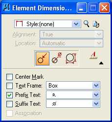
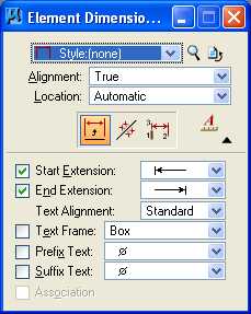
K.1.g. From the Element Dimensioning palette,
choose Style: (none), choose the Dimension Radius icon
(leftmost icon)  and deselect Center Mark, deselect Text Frame,
select Prefix Text, set Prefix Text to R,
and deselect Suffix Text.
and deselect Center Mark, deselect Text Frame,
select Prefix Text, set Prefix Text to R,
and deselect Suffix Text.
K.1.h. Move the cursor until the dimension is similar to the plot below and press the Data button to accept the placement.
K.2. Use MicroStation to dimension the second circular arc (green circular arc) with color set to green (color=2).
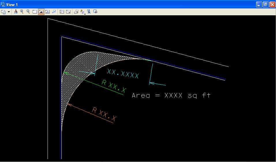
K.3. Use MicroStation to dimension the taper section line (light blue line) with color set to light blue (color=7).
K.3.a. Place the cursor over the light blue line and press the Data button.
K.3.b. From the Element Dimensioning palette,
choose Style: (none), set Alignment to True, set Location to
Automatic, choose the Dimension
Element icon
(leftmost icon)
 and select Start Extension,
set Start Extension to Arrow, select End
Extension, set End Extension to Arrow, set Text Alignment
to Standard, deselect Text Frame,
deselect Prefix Text, and deselect Suffix Text.
and select Start Extension,
set Start Extension to Arrow, select End
Extension, set End Extension to Arrow, set Text Alignment
to Standard, deselect Text Frame,
deselect Prefix Text, and deselect Suffix Text.
K.3.c. Move the cursor until the dimension is similar to the plot below and press the Data button to accept the placement.
L. Turn Level 1 display on.
M. Place a landscape oriented rectangle centered around the intersection in 8.5" by 11" proportion (230 feet by 180 feet) with level of Level 1 (level=Level 1), color of white (color=0), style of solid (style=0), and weight of 0 (weight=0).
N. Place the title "Lab Assignment 04" at the top right and your name, class name, and assignment due date in the lower right at a text height, text width, and text line spacing of 5 feet with font of 3 (font=ENGINEERING), justification of Center Center, level of Level 1 (level=Level 1), color of white (color=0), style of solid (style=0), and weight of 0 (weight=0).
O. Place a fence from the rectangle placed in Step M and plot the drawing using ENGR-SC2-Laser-2 and options for Fence, Monochrome, Letter, Landscape, a Scale of 25 ft / in, and Settings -> Print Attributes -> Fence boundary off and Print border on.
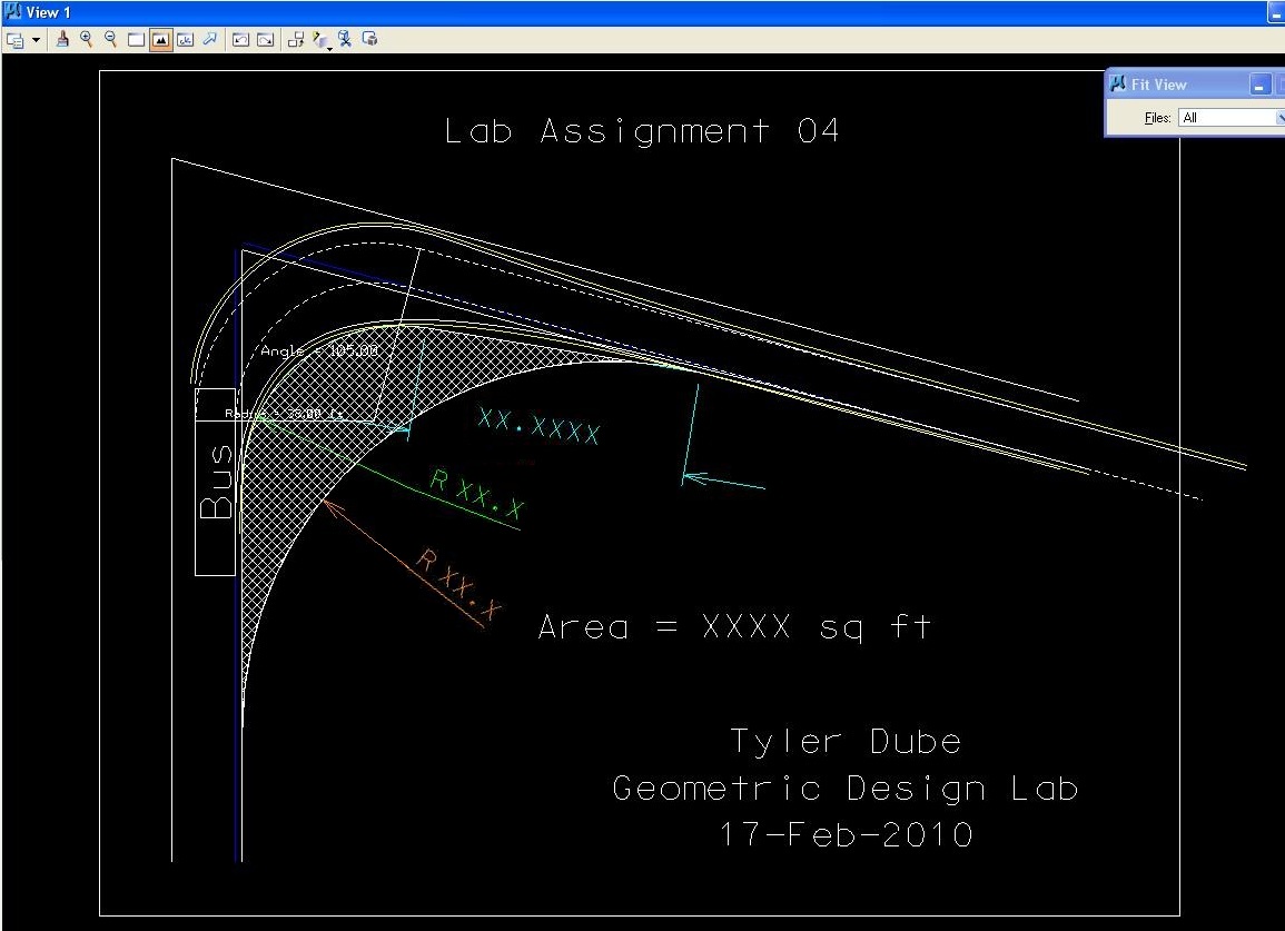
Pavement Edge Design with a Simple Arc of a Circle and with a Taper Section and an Arc of a Circle Plot
P. Exit MicroStation.
Q. Reboot the computer.
Geometric Design Lab Spring 2011 web page
Latest Update: 11 Feb 2011 02:50 PM